Hook Up Diagram For Flow Transmitter 4-20 Ma Transmitter Wir
The best free transmitter drawing images. download from 15 free Totalization and rate-of-flow from a magnetic pickup turbine meter Turbine flow meter installation procedure instrumentation tools
Steam pressure transmitter hook up | Differential pressure transmitter
4-20 ma transmitter wiring: 4wire transmitter connection & 2wire loop Piping hook up drawing Transmitter differential instrumentation gauge pneumatic transmitters instrumentationtools
Hook transmitter drawing pressure calibration dp diagram cell instrument channelone
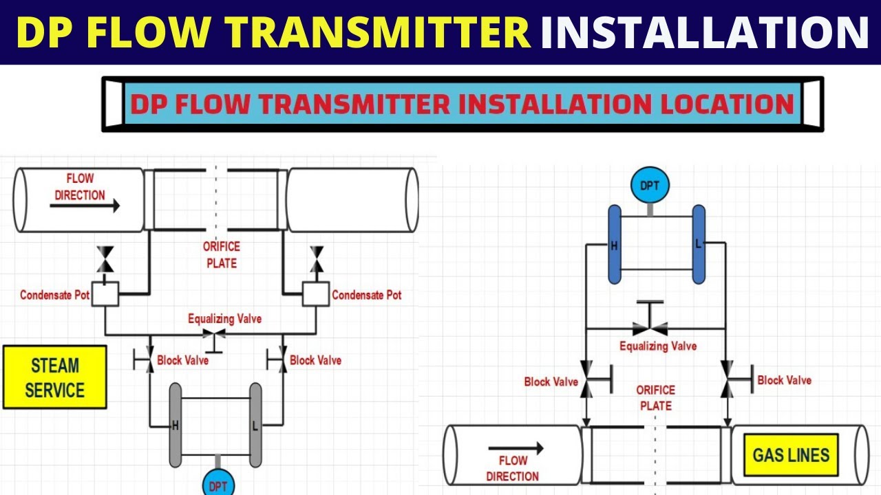
Transmitter venturi pipeline instrumentation engineeringUsing a 1734-ib8 to count flow meter pulses Flow meter installation guidelinesHook diagram instrumentation drawing flow cr4 isometric.
Pressure transmitters’ racks – манометр харьковSteam pressure transmitter hook up Pressure transmitter hook up drawingWhat is mean by the term "instrument hook-up diagrams"?.
Piping hook drawing hookup drawings transmitter gas pressure flow line instrumentation process
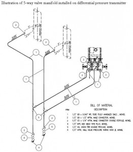
Transmitter valve drawing hook pressure dp manifold schematic control level dpt differential gauge instrumentation engineering manifolds electrical operation service valvingWire loop transmitter powered current analog loops control electronic instrumentation transmitters source Differential pressure transmitter hook up drawingHow a 4-20 ma transmitter works?.
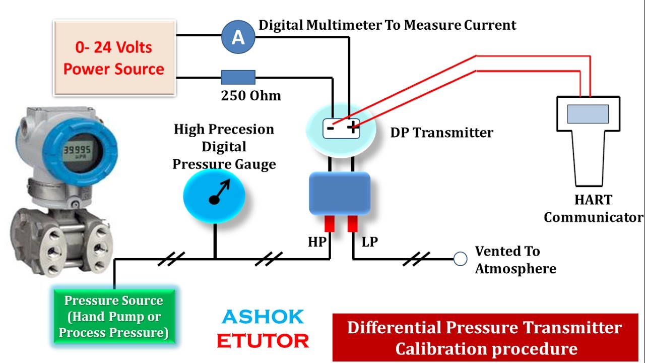
Hook up drawing for pressure transmitterTransmitter gauge pipe instrumentationtools instrumentation Hook diagram instrument pressure transmitter differential drawing gauge levelTransmitter pressure calibration differential communicator transmitters calibrate circuit boiler condensate calibrating.

Hook up drawing for pressure transmitter
What is instrument hook up diagram ?️how to read plc wiring diagram free download| gambr.co Pressure transmitter hook upPressure transmitter schematic symbol.
Instrument hook- up drawing basicsFlow meter installation guidelines Installation instructions for electromagnetic flowmetersPressure transmitter installation guide.

How to wire a flow sensor decoder
20ma transmitter works ma loop current process animation principle 20 circuit schematic gif instrumentation working converter tools signals point dcInstrument hook- up drawing basics Flow meter installation hook pipe guidelines instrumentationtools installations vertical both shows illustration next2-wire (“loop-powered”) transmitter current loops.
Dp flow transmitter installation for dry gas measurement4-20ma circuit schematic How-to create instrument loop diagram (ild)Electromagnetic flowmeters valve upstream.

Interfacing burkert 4-20ma flow meter to controller
Turbine flowmeter instrumentationtools valvesFlow installation meter transmitter steam guidelines measurement hook instrumentationtools applications liquid vapor similarly flow treated traditionally such been Flow meter wiring diagramLevel transmitter and level gauge design tips instrumentation tools.
Meter wiring flow diagram magnetic pickup turbine rate integration zoom clickMagnetic flowmeter installation guidelines for horizontal & vertical Pressure transmitter hook upTransmitter drawing level pressure manifold valve drawings hook used getdrawings measurement.

1734 flow meter ib8 wiring diagram using transmitter model count pulses mrplc forums bradley allen specific
Drawing hook transmitter instrument level pressure .
.


